

Spherically Reprojecting the Artemis II Moon onto the Earth's Moon — How I Compared Two Views of the Same Sphere
I was looking at the Artemis II crew's moon photos and something immediately looked off. The moon looked full-ish, but it wasn't the same moon I'm used to seeing. The mare distribution was wrong, features near the limb were unfamiliar — it looked like someone had taken our moon and rotated it. Which, from the spacecraft's perspective, is exactly what happened.
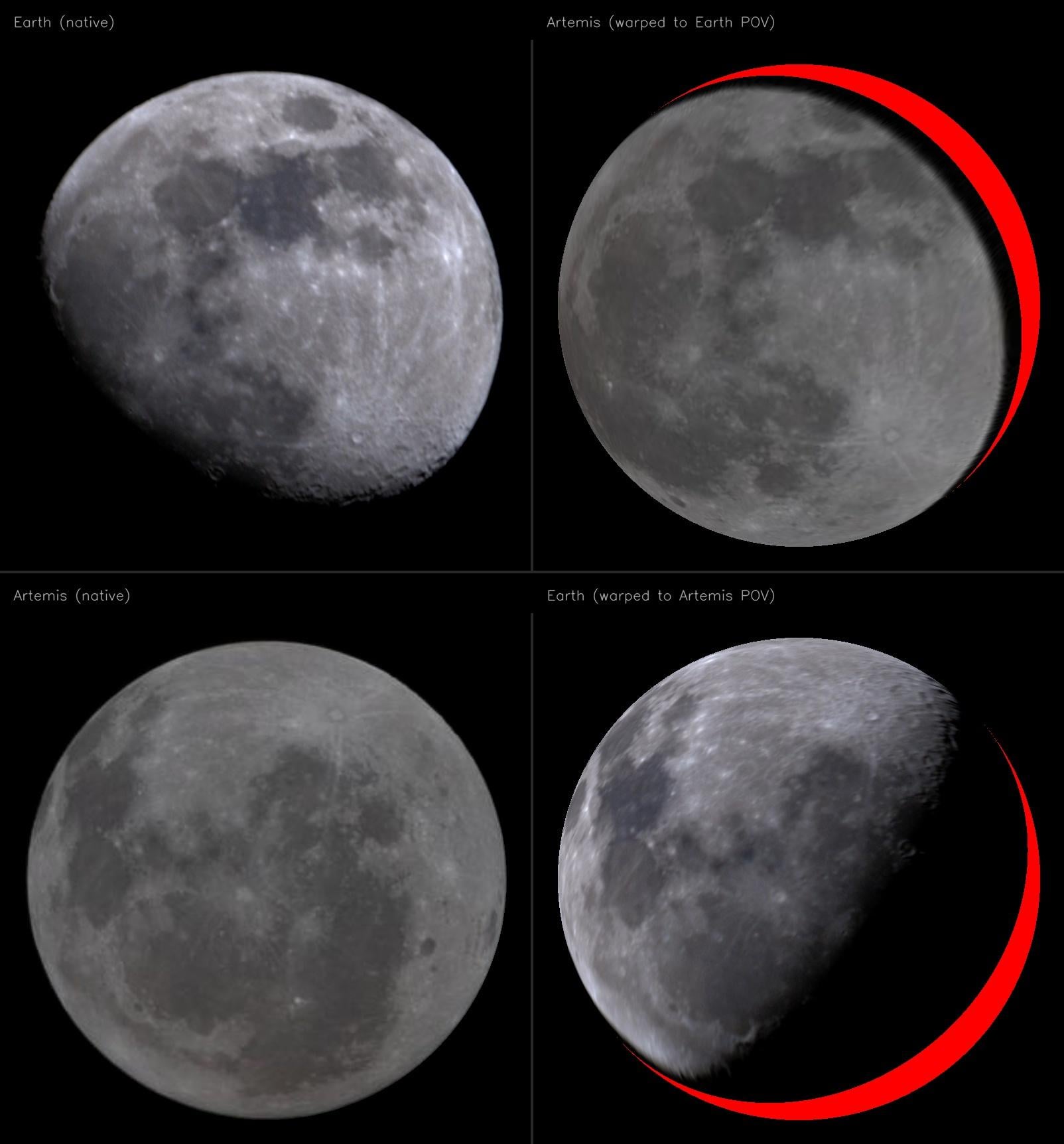
So I wanted to do a proper comparison: take my own Earth-based moon photo, take the Artemis II image, and warp one into the other's reference frame so you can directly see what changed. The problem is that naive 2D alignment (homography, affine transform) can't do this correctly — the moon is a sphere, and the distortion between two views of a sphere is fundamentally non-planar. A homography fits a plane and progressively fails toward the limbs.
Here's how I did it properly, with a full 3D spherical reprojection.
Step 1: Detect and Normalize the Moon Disk
Both images are just a bright disk against black sky. Standard approach: convert to grayscale, Gaussian blur, threshold at a low value (~30), find the largest contour, and fit a minimum enclosing circle. This gives me the center (cx, cy) and radius r in pixel coordinates for each image.
Step 2: The Key Geometric Insight — Orthographic Projection
Because the moon is ~384,000 km away and ~3,474 km in diameter, the projection is effectively orthographic (the angular size is ~0.5°, so perspective effects are negligible). Under orthographic projection, the mapping from a point on the unit sphere to a pixel on the disk is trivially simple:
For a point P = (x, y, z) on the unit sphere (where z points toward the camera), the projected disk coordinates are just:
u = x
v = -y    (flipped because pixel y increases downward)
And going the other direction — lifting a disk pixel back to 3D:
x = u
y = -v
z = sqrt(1 - u² - v²)    (if u² + v² ≤ 1, i.e., we're inside the disk)
This is the crucial step. Every pixel on the moon disk corresponds to a unique point on the visible hemisphere of the unit sphere, and we can compute that 3D point trivially. Points outside the disk (u² + v² > 1) are sky — they don't map to the sphere at all.
Step 3: Feature Matching Between Views
To find the rotation between the two views, I need corresponding points. I used SIFT (Scale-Invariant Feature Transform) on CLAHE-enhanced (Contrast Limited Adaptive Histogram Equalization) grayscale crops. CLAHE is critical here because raw moon photos have low surface contrast — the dynamic range is mostly consumed by the overall albedo gradient from center to limb. CLAHE locally enhances crater rims, ray systems, and mare boundaries, pulling SIFT's keypoint count from ~20 to ~6,500 per image.
After matching with a ratio test (Lowe's method, threshold 0.8), I got 158 good 2D correspondences.
Step 4: Lift Matches to 3D and Solve for Rotation (Wahba's Problem)
Each matched pair gives me a point in image A's disk and the corresponding point in image B's disk. Using the orthographic projection formula from Step 2, I lift both to 3D unit sphere coordinates. Now I have ~158 pairs of 3D points that should be related by a pure rotation R ∈ SO(3):
P_artemis = R · P_earth
This is Wahba's problem (1965), and the closed-form solution uses SVD. Form the cross-covariance matrix:
H = Σ P_earth_i · P_artemis_i^T
Compute the SVD: H = U · S · V^T
The optimal rotation is:
R = V · diag(1, 1, det(V · U^T)) · U^T
The middle diagonal matrix ensures det(R) = +1 (proper rotation, no reflections). This minimizes the sum of squared errors across all correspondences and has a clean geometric interpretation: it finds the rotation that best aligns the two point clouds on the sphere in the least-squares sense.
Step 5: RANSAC Refinement
Not all SIFT matches are correct, and outliers can pull the rotation estimate. I wrapped the Wahba solver in RANSAC: sample 3 random correspondences, solve for R, count how many of the remaining matches have residual error below 0.08 on the unit sphere (~4.6°), keep the best. After 2,000 iterations, 98 of 158 matches were classified as inliers, and refitting on just the inliers gave the final rotation matrix.
Result: The total 3D rotation between the two views is 95.6° in SO(3), but that number is misleading on its own. An SO(3) rotation includes roll (spinning around the viewing axis), which changes the image orientation but not which terrain is visible. The quantity that matters for visibility is the boresight separation — the angle between the two cameras' viewing directions — which is simply arccos(R₃₃) = arccos(0.881) ≈ 28.2°. So the spacecraft was about 28° around the moon relative to Earth. The full rotation also includes a substantial image-plane twist; these components do not add linearly in SO(3), so the remaining contribution shouldn't be read as simply 95.6° − 28.2°. The full rotation matrix:
R = [[ 0.021  -0.952  -0.306]
     [ 0.928  -0.095   0.361]
     [-0.373  -0.292   0.881]]
Step 6: Spherical Reprojection — Rendering from Each Viewpoint
This is where it all comes together. Say I want to render the Artemis image as it would appear from Earth's viewpoint:
For every pixel (u, v) in the output disk:
- Lift to 3D in Earth's reference frame: P_earth = (u, -v, sqrt(1 – u² – v²))
- Transform to Artemis's frame: P_artemis = R · P_earth
- Check visibility: If P_artemis.z > 0, this point was on the visible hemisphere from Artemis's camera — we have data. If P_artemis.z ≤ 0, this point was on the back side of the moon from Artemis — no data exists.
- Sample or fill: If visible, project back to 2D disk coords (P_artemis.x, -P_artemis.y) and bilinearly interpolate from the Artemis source image. If not visible, fill red.
The same process works in reverse to render the Earth image from Artemis's viewpoint — just use R^(-1) = R^T (rotation matrices are orthogonal, so the inverse is the transpose).
Why the Red Matters
The red fill is not a cosmetic choice — it's an epistemological one. It represents genuine absence of information. That part of the lunar surface was physically behind the limb from that camera's perspective. No photons from that terrain reached the sensor. Black would be ambiguous (is it space? shadow? data?). Red says unambiguously: "real terrain exists here, but this image has nothing to tell you about it."
The overlap between two hemispheres separated by a ~28° boresight angle follows from the geometry: the projected disk overlap fraction is (1 + cos(δ))/2 = (1 + R₃₃)/2 ≈ 94%, leaving a ~6% crescent of unknowable terrain. This is a direct geometric consequence of how far apart the two viewing directions are.
Why the Gibbous Phase Makes This Work
One thing I didn't plan but turned out to be the best part: the Earth image isn't a full moon. It's gibbous — part of the disk is in shadow. That accident creates three visually distinct zones in the warped output, each with a different physical meaning:
- Lit terrain — the sun is illuminating this surface, the camera captured it, and you see real albedo and topography. Craters, mare, ray systems — all resolved.
- Dark terrain (shadow) — the surface is physically there, and the camera's line of sight reaches it, but the sun isn't illuminating it. This is real data — real zeros. If you cranked the exposure, that terrain would reveal itself. It's photometrically dark, not missing. The moon is tidally locked — it rotates exactly once per orbit, so the same hemisphere always faces Earth. What changes with lunar phase is just where the terminator sits on that fixed hemisphere. At new moon, the entire near side is in shadow — maximum darkness. At full moon, it's fully lit. But you're always looking at the same face.
- Red (no data) — terrain that was behind the limb from this camera's vantage point. In this visualization, red means one thing: the source image has no data here. For most of the red crescent, this is genuine far-side terrain that Earth never sees — the moon's tidal locking ensures the same hemisphere always faces us. No phase change helps: if a different phase could reveal far-side terrain, that would imply the moon is rotating relative to Earth — which would mean it isn't tidally locked. The far side wasn't even photographed until Luna 3 flew around it in 1959. (A small caveat: due to lunar libration — slight wobbles in the moon's orbit — Earth can actually see about 59% of the surface over time, not exactly 50%. So a few red pixels right at the boundary might occasionally peek into view from Earth. But the bulk of the crescent is true far side.) The red exists because Artemis II was physically ~28° around the moon relative to Earth. The size of the crescent is a direct geometric consequence of that boresight separation.
The gibbous phase is what makes this visualization work so well. It spatially separates the photometric boundary (the terminator — where sunlight stops) from the geometric boundary (the red edge — where one camera's data runs out). At full moon, those two boundaries collapse onto each other at the limb and you lose the distinction. At new moon, the entire near side is shadow, so everything merges into darkness. The gibbous phase sits between these extremes, letting you visually trace the gradient from lit terrain through shadow and into red — three physically distinct zones, each governed by different physics, all visible at once.
Results
The reprojection confirms what I was seeing intuitively — the Artemis II crew was looking at the moon from about 28° around relative to Earth, so a visible slice of terrain in their view is stuff we essentially never see from Earth, and vice versa. The mare patterns shift, limb features that are normally razor-thin become fully resolved, and the overall gestalt of "the moon" changes in a way that's immediately uncanny even before you can articulate why.
Tools: Python, OpenCV (SIFT + CLAHE), NumPy, SciPy (bilinear interpolation via map_coordinates). The whole pipeline runs in a few seconds.
by jimmystar889
2 Comments
The image of the moon was taken with the Seestar S30 pro
Sometimes I think we have a little too much time on our hands. Very cool